NTBD: a step by step guide
Pubblicato il
Fiorella Sibona
Roboticist Wannabe
Index
Hi everyone! It’s me again, Fiorella and, with this post, I’d like to present my Master Thesis work for the M.Sc. in Mechatronic Engineering degree at Politecnico di Torino, “Development of a Standard Architecture to enable Fast Software Prototyping for Robot Arms”, and provide a step by step guide as clearly as possible (hopefully!) for using and re-using the developed architecture, called NTBD. In the first part I present the proposed architecture as you will find it browsing the github project. In the second post, instead, there will be a tutorial on how to use the architecture integrated with the chosen Open-Source robot arm, having a PC with Intel processor (or an ARM-processor host). Finally in the third article I’ll explain how to exploit NTBD using another manipulator different from the one I’ve presented, highlighting the limits.
Part I: an overview
Motivations
The idea of my thesis came up noting that, when it comes to rapid prototyping, hardware has always has plenty valid choices, for example the Open-Source board Arduino and RaspBerry Pi; for what concerns Robotics, there are countless Open-Source projects for robot contruction, equipped with instructions, advices about the control hardware to be used, necessary pieces (which may be 3D printed) and BOM lists. For what regards the software, however, there isn’t a standard architecture upon which build your robotic application easily. Here comes into the picture NTBD, with the aim of developing robot arm applications.
NTBD: Name To Be Decided
Well, yes, here it is the so-longly-searched name in all its glory! After afternoon-sessions trying to find a cool and catchy name, that’s the result… 
Anyway, I think that the most important part is content. Talking about content, I’ll now give a brief top-down overview of NTBD.
NTBD - Conceptual Level
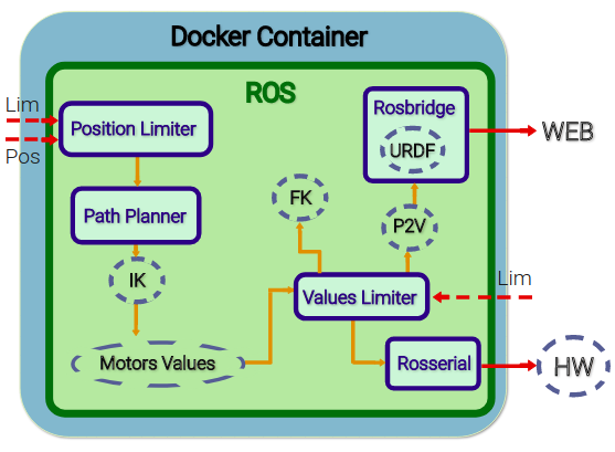
The architecture is composed of several elements among which we have abstract components, that are generic user-implemented components . I subsequently list the role that each abstract component takes on:
- IK & FK: they implement the inverse kinematics and forward kinematics for the manipulator end effector.
- URDF: it is a file (Universal Robot Description Format) which describes the kinematic structure of the arm in order to define its simulation model.
- P2V: here the joint angles are converted to obtain the corresponding values to move the simulation model accordingly.
- Motor Values: in this element the joints values and the gripper value (if present) are put together into one single array.
- HW: this component represents the used hardware for the manipulator control, in this case an Arduino board.
The following are the robot arm structure-independent components:
- Position Limiter: this element has the role of limiting the desired position determined by the lower and upper limits of the Cartesian coordinates x,y,z.
- Path Planner: I have chosen, for the sake of simplicity, to plan the end effector path in a linear fashion, assuming that no obstacles are present.
- Values Limiter: also the motor values must be limited, so as to avoid damages and unexpected behaviour.
- Rosserial: thi element represents the importance of the Rosserial tool, needed to bridge a serial connection with the rapid prototyping control platform.
- Rosbridge: this component represents the ROS tool Rosbridge, which allow our manipulator simulation through the integration of the ROS system with the WEeb, using a JavaScript library, roslibjs.
NTBD - Docker Level
The architecture is portable thanks to its definition in a Docker container, which guarantees its execution always in the same way, with the only requirement of a Docker compliant system. Those who already have some basic knowledge of Docker, surely know that a Docker application is developed starting from a base image which usually is an Operating System image. In this case, the starting image is Ubuntu 16.04 with ROS Kinetic Kame (10th ROS distribution, 2016) installed on it, gathered from the HotBlack Robotics github. As can be seen from the NTBD repository onDocker Hub, there are two layers which make up the architecture, base and manipulator. The first one contains the architecture’s elements which are commont to all robotic arms (Position Limiter, Path Planner, Values Limiter, Rosserial e Rosbridge); upon this layer is built the second image in which the abstract components are implemented.
NTBD - ROS level
The components previously presented have been implemented in ROS, Robot Operating System, as Python nodes. I assume that the reader knows the basic dynamics of ROS framework, in order to avoid expatiating in further explanations and proceed to the listing and relative explanation of this architecture’s nodes and topics.
In the Figure we can see nodes and topics involved in NTBD dynamics. 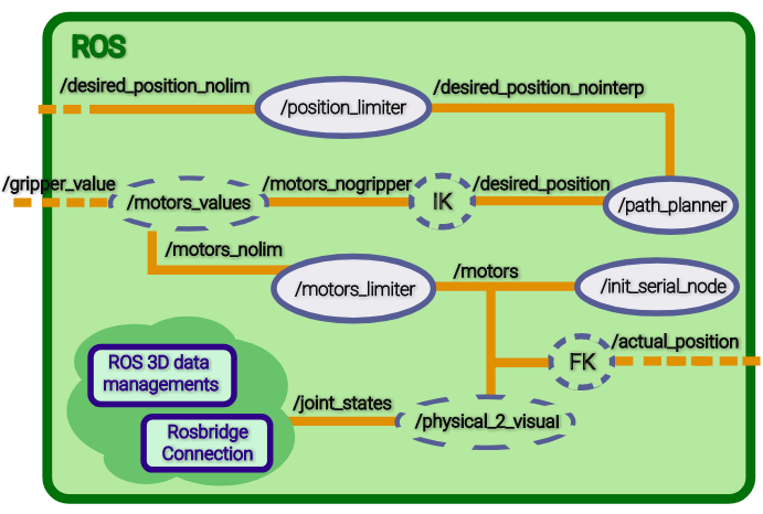 The following table presents topics and relative ROS messages.
Note:
- Motors_Array is a custom ROS message type, created to enhance the message content and have a simple structure.
- the /girpper_value message tipe depends on the user implementation.
| Topic | ROS Message Type |
|---|---|
| /desired_position_nolim | geometry_msgs/Point |
| /desired_position_nointerp | geometry_msgs/Point |
| /desired_position | geometry_msgs/Point |
| /motors_nogripper | Motors_Array |
| /gripper_value | std_msgs/String |
| /motors_nolim | Motors_Array |
| /motors | Motors_Array |
| /actual_position | geometry_msgs/Point |
| /joint_states | sensor_msgs/JointState |
- Topic desired_position_nolim: the desired position is published on this topic, as a Point message.
- Nodo /position_limiter: here the values which lie outside the limits (defined as ROS parameters), are saturated such that errors due to unreachable positions are avoided.
- Topic /desired_position_nointerp: the positions, “filtered” by node /position_limiter, are oublished on this topic.
- Nodo /path_planner: the aim of this node is to compute the linear interpolation between two consecutive positions published on /desired_position_nointerp.
- Topic /desired_position: here the sequence of space points computed by the path planning node is published.
- Nodo /IK: the desired position is converted in motor values (angles, in the case of servo-motors).
- Topic /motors_nogripper: the values obtained in /IK are made available here.
- Topic /gripper_value: provides in output the desired value for the robot arm gripper, in this case the gripper can be open or closed.
- Nodo /motors_values: here the motors and gripper values are combined in a unique data vector.
- Topic /motors_nolim: the set of all desired values is published in this topic.
- Nodo /motors_limiter: this node reads the motors values and, if necessary, it limits them by comparison with the ROS parameters- defined limit values. This node is crucial in the case that the user wishes to controle the robor in the joint space directly.
- Topic /motors: the limited values are finally available in this topic.
- Nodo Rosserial /init_serial_node: this node, which corresponds to the /serial_node node, permits to establish a connection between the serial node loaded on the hardware platform (Arduino in this case) and the ROS system running on the PC. Indeed the motors values are read by the specific topic and processed by the board in order to move the servos.
- Nodo /FK: motors values can also be used for computing the forward kinematics, leading in fact to the actual reached position, which can be differnt from the desired one, due to physical limits.
- Topic /actual_position: the reached position is published here.
For what concerns the robot simulation on a web page, I had to make available in a server the robot arm URDF file and the HTML file for the application. The adopted solution consisted in bringing up a server, within the containerized environment, using nginx, an Open-Source web server which can be used to provide on the network HTTP contents. In order to display the simulation on the host machine browser, the port 80 of the container has been mapped to a host port of choice, e.g. 1234 (in the final versione, port 80 is mapped on the host standard port i.e. port 80). The nginx default root folder (/var/www/html) contains the HTML document, where the Rosbridge and ROS interactions happen and the where the URDF necessary for rendering is available. 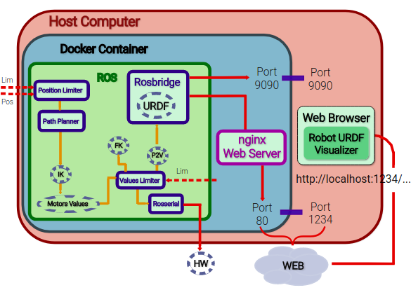
Going back to the ROS level description, the following are nodes and topics involved in the robot arm simulation:
- Nodo /physical_2_visual : this node is one of the abstract components, thus dependent on the manipulator choice. It is a conversion node which maps the physical values, provided by topic /motors to the equivalent visualization values.
- Topic /joint_states: here the visualization joint values are published.
From here on, the topic message management and nodes are the typical ones for ROS dealing with 3D data: the joint values are passed to the /robot_state_publisher topic, which gives in output messages of geometry_msgs/Transform type, exploiting the tf2 ROS package, that enables the user to track the coordinate systems in time. These information are then discoled to Rosbridge; since nodes and topics involved in this part are pretty standard, I won’t explain it further. 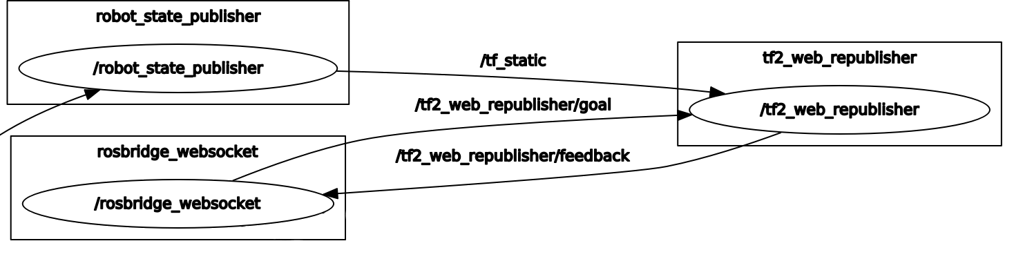
Connecting to “ourselves” from the browser, on the defined port, we can see the arm model moving together with the physical manipulator. The Rosbridge connection is initiated on the default port 9090 on which another computer can interact with the ROS system by publishing and subscribing on its topics.
Part II: tutorial
In this article I will explain how to reproduce the project, complete of robot arm integrated to the NTBD architecture, introduced in post Part I.
Ingredients
We’ll need:
- 1 3D printed EEZYBOT MK2 arm, along with the needed servo-motors (3 mini-servos, 1 micro-servo)
- 1 Arduino board (in my case I have used a Mega ADK 2560)
- 1 PC with Intel processor on which install Docker
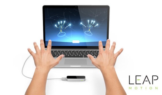
- 1 Leap Motion controller to use one of the implemented robotic applications.
- 1 external power supply, 2A-7.5V
- 1 Breadboard
- Jumpers to taste
Remark: This tutorial refers to the Docker Image for Intel hosts but also the ARM Image is available (can be deployed on Raspberry 3). To obtain the ARM version, when a command is required or a document is reffered to, it is sufficient to replace the word intel with rpi3.
1. Print the Robot Arm
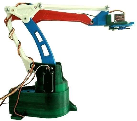
The robot arm which I have chosed is EEZYbotARM MK2, an Italian Open-Source project by Carlo Franciscone, Design Engineer e Maker.
Following the instructions available on Thingiverse and Instructables for this project, I successfully completed the 3D printing and mounting of the manipulator. I have used the Cura software with parameters configured for a DeltaWASP printer. For the DeltaWASP printer, download the following profile and load it on Cura following this guide.
Following are reported the most significant parameter for printing the neceassary pieces and to improve their definition:
| Parameter | Value |
|---|---|
| Infill | 30-100%. I’d recommend printing with 30% infill only the robot part which are undergoing few stress whereas the small mechanical parts should be printed with 100% infill. |
| Printing Temperature | 200-210°C |
| Build Plate Temperature | 40°C |
| Filament Diameter | 1.8 mm |
| Print Speed | 60 mm/s |
| Infill Speed | 80 mm/s |
| Travel Speed | 150 mm/s |
| Support | Enabled |
| Platform Adhesion | Enabled |
This is the result:
2. Download the Arduino Sketch
On the NTBD github page you can find the myServoControl_ntbd.ino sketch which has to be uploaded on the Arduino board. In my case I have used an Arduino Mega ADK 2560. 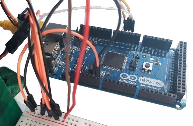
3. Download Docker
For Ubuntu use this link.
4. Download the Docker Images
At this step, in order to download the NTBD images it is sufficient to execute the following command on the command line, so as to retrieve them from Docker Hub, using the docker pull command:
docker pull hbrobotics/ntbd_base:intel
docker pull hbrobotics/ntbd_manipulator:intel
5. Connections
As you can see from the sketch, the servomotors, numbered as in Figure, are connected to the Arduino as reported in the table below.
| Servo | Arduino Pin |
|---|---|
| 1 | 2 |
| 2 | 3 |
| 3 | 4 |
| 4 | 5 |
To make all servomotors mode at the same time without overloading the board, connect it to the external power supply at 7.5 V/ 2 A. Connect the mini-servos to the breadboard having the V+ connected to the Vin Arduino pin and V- connected to one GND (ground) Arduino pin of choice.
To avoid overheating the micro-servo, connect its V+ to the 5V Arduino pin and its V- to a GND pin.
WARNING: always check that the ground is common to all components (Breadboard GND = Arduino GND ).
Connect the board and the Leap Motion controller to the PC via USB cable.
To correctly install the Leap Motion drivers for Ubuntu 16.04, follow this guide along with this slight edit.
6. Run the Docker Container
Now that all external devices are connected, download the .yaml file for the ntbd-manipulator:intel image that is the one we are interested in. So as to boot the container (where the Web applications lie), you have to execute the following command within the folder in which the .yaml file is contained, exploiting the Docker Compose tool:
docker-compose -f docker-compose.hbr_ntbd_intel.yml up
7. WebApps for NTBD and siBOT
The combination of NTBD with the EEZYBOT arm controlled with ROS is what I have called siBOT. 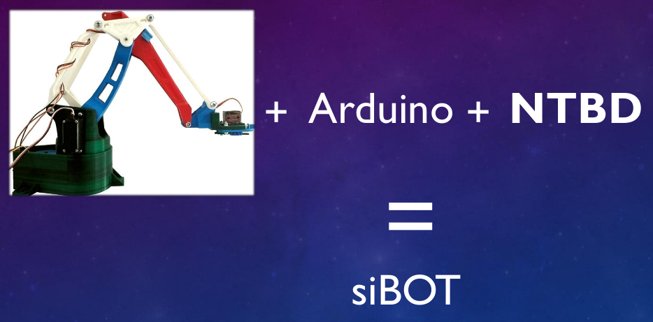
Once the container has been run, open a browser page and connect to the loopback address, localhost, in order to connect to our computer: indeed the web application server is on our PC. Having called the HTML file “index.html”, by connecting to our IP address on the default port 80 (as expected, having mapped the container port 80 to the host port 80), the web address homepage will be indeed the WebApp NTBD-Visualizer, providing a link to the Leap Motion application.
8. Play with the WebApps
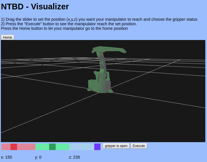
Simulation and control using NTBD - Visualizer Application
Now you are provided with the simulation application from which you can impose a desired end effector position, moving the Cartesian coordinates sliders; clicking on the Execute button you will see the arm model moving together with the phisical arm.
Remark: the input values inserted by the user through the NTBD - Visualizer WebApp, are used to control both the simulation model and the physical arm.
Leap Motion Application
If you want to try out the second developed application, just click on the “NTBD Leap Motion WebApp” link which will open a new web page. By keeping this window/tab selected, you can see that positioning your hand above the Leap Motion controller, the space positions are interpreted and sent to the physical robot that will emulate your hand movements. 
Remark: to open and close the gripper simply open and close your hand!
Part III: integration with other manipulators
In order to adapt the NTBD architecture to a another manipulator, different from EEZYBOT, it is necessary to re-define the architecture abstract components. Furthermore I assume that the control platform is an Arduino board. The abstract components are implemented in the ntbd_manipulator Docker Image and, as explained in post “Part I: an overview”, they depend on the chosen robot arm and thus require editing according to the new structure. Remarks:
- I suggest reading Part I and Part II in order to understand what has to be modified to integrate your manipulator with NTBD and how to connect external devices for the control and the WebApps.
- To build the Docker Images it is necessary to install Docker. In this tutorial I assume that the reader has knowledge about developing apps with Docker. For some pieces of advice, read the Appendix.
1. Edit the NTBD abstract components
It is necessary to download the NTBD project from github so as to edit the following files before proceeding with the build of the new ntbd_manipulator Image:
- joint_names_sibot_urdf.yaml: in this file are defined the robot joints names, useful for ROS messages exchange. This definition is used, for example, in node physical_2_visual, which must be modified accordingly.
- /meshes/: this folder containes the meshes needed for the manipulator visualization, in [STL](https://it.wikipedia.org/wiki/STL_(formato_di_file) format.
- siBOT_noEE.urdf: this file contains the URDF definition for the new robot armd; it can thus be renamed with the only precaution of changing the file name in the launch file NTBD_launch.launch.
- index.html and ntbd_lm.html define the Web Applications and must be modified depending on the new configuration (e.g., with new limits).
- IK, FK, motor_values and physical_2_visual: these files are all manipulator dependent; for further information about their role, » go to Part I: an overview.
- NTBD_launch.launch: this file must be edited to update the end effector position coordinates limits and motors limits.
- myServoControl_ntbd.ino: obviously, changing the manipulator, also the physical configuration will most likely change (number and type of motors) and consequently the Arduino sketch must be edited.
Remark:
- the ROS package manipulator_urdf, which contains all the info needed for using URDF definition, can be automatically generated starting from the robot assembly file, exploiting the SolidWorks to URDF Exporter tool.
- In the event that a file name must be modified, it must be taken into account that such file could be “called” within another file and the latter should be edited accordingly. My advice is to avoid re-naming file in order to prevent errors.
2. Building the new Image
Once the necessary files have been mofidied, it’s time to build the new Docker Image. Enter into the NTBD_manipulator folder in which we have the Dockerfile.intel file, and execute the following command.
docker build -t ntbd/manipulator:intel .
3. Run the new Container
After connecting all external devices, run the container executing:
docker-compose -f docker-compose.intel.yml up
which exploits the Docker Compose tool with configuration specified in the docker-compose.intel.yml file.
The NTBD integration with a new robot arm ends here, for further information about the WebApp usage, see Post Part II: tutorial.
Appendix: Docker prod vs Docker devel
When working with Docker, it is convenient, for the sake of organization, to use a Development Image and a Production Image. The latter is the final version of the Docker application, ready for release, whilst the former is used during the development phase. A common Image is built on which the Prod and Dev versions are generated and, with some tricks, it is possibile to harness the *caching * mechanism provided during the building stage. Indeed, if the edited files are still in debug phase, at each Image build, the layers (even if previously built up) will be re-built.
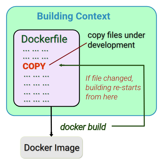
It is thus suggested to have all files still in dev stage in a single folder, shared among the host system and the container: through a bash script, executed at boot time in the container, the files are copied into the container. This clearly increases the boot time but also avoids the re-building issue. The Prod Image, which for NTBD is the one provided on Docker Hub, copies the definitive files from the building context (the folder containing all necessary resources for the container execution) to the container file system, since now all files should be at their final version.
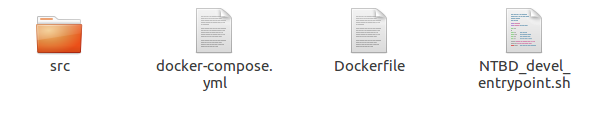
The following is a building context example:
Here I provide the NTBD_devel_entrypoint.sh bash file content, used for my development version:
#!/usr/bin/env bash
set -e
echo "export TERM=xterm" >> ~/.bashrc
echo ". /opt/ros/kinetic/setup.bash" >> ~/.bashrc
echo ". /catkin_ws/devel/setup.bash" >> ~/.bashrc
# Source form host:
# NTBD_core scripts & launch
cp /src/IK /catkin_ws/src/ntbd_core/scripts/IK
cp /src/physical_2_visual /catkin_ws/src/ntbd_core/scripts/physical_2_visual
cp /src/FK /catkin_ws/src/ntbd_core/scripts/FK
cp /src/motors_values /catkin_ws/src/ntbd_core/scripts/motors_values
# Make scripts executable to be used as nodes!
cd /catkin_ws/src/ntbd_core/scripts/
chmod +x IK && chmod +x physical_2_visual && chmod +x FK && chmod +x motors_values

cp /src/NTBD_launch.launch /catkin_ws/src/ntbd_core/launch/NTBD_launch.launch

# NTBD_urdf
cp -rf /src/manipulator_urdf/ /catkin_ws/src/manipulator_urdf/
# setup ros3djs config (comprehends nginx config)
cp -rf /src/manipulator_urdf/ /var/www/html/manipulator_urdf/
cp /src/NTBD_viz.html /var/www/html/NTBD_viz.html

cp /src/ntbd_lm.html /var/www/html/ntbd_lm.html

cp -rf /src/ros3djs/roswebconsole/ /var/www/html/roswebconsole/

source /catkin_ws/devel/setup.bash
cd /catkin_ws/ && catkin_make

# setup ros environment
 source /opt/ros/kinetic/setup.bash
 source /catkin_ws/devel/setup.bash

# start nginx
service nginx start

# Launch my ROS nodes and ros3djs URDF visualization
roslaunch ntbd_core NTBD_launch.launch

exec "$@"
Fiorella Sibona
Roboticist Wannabe